

8 Test the lock and see if it works
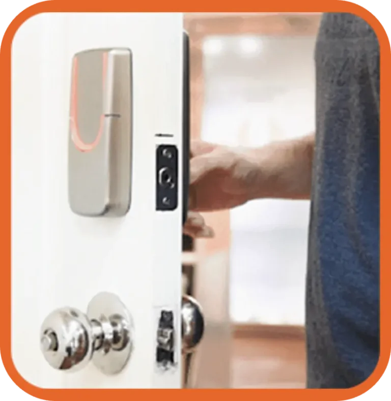
Download the SGUDA APP and pair it with the lock to test all functions.


Follow the installation guide for your SGUDA smart lock. Check the required tools and installation steps before getting started.
❌Do not use a power drill.
❌Do not insert the batteries until installation is complete.
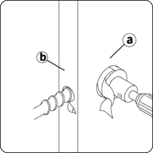
Make sure the front and back units can sit completely flush against the door after installation.
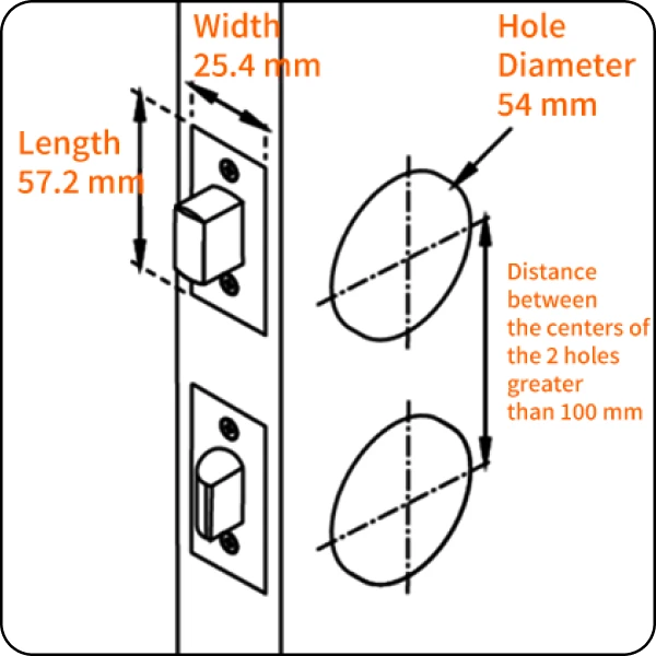
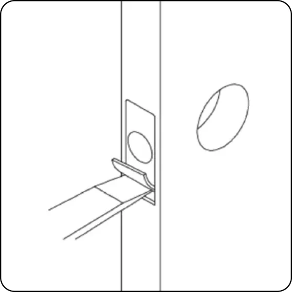
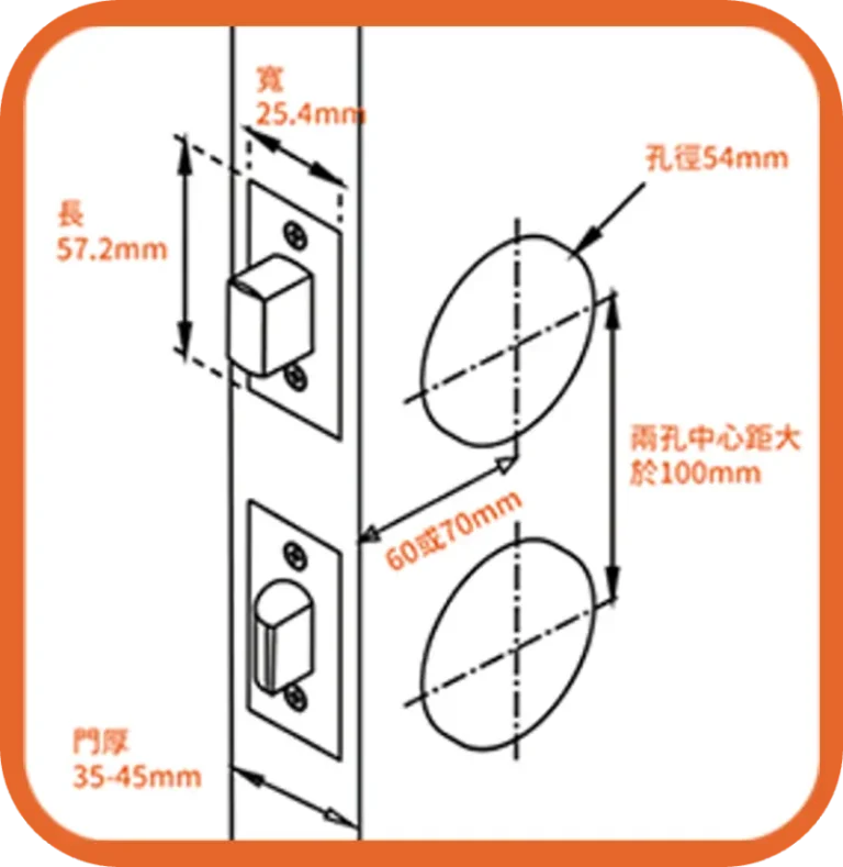
A 54 mm (2-1/8″) hole is required above the door handle, along with a latch faceplate recess on the edge of the door:
Download the drilling template and check the required dimensions before installation.
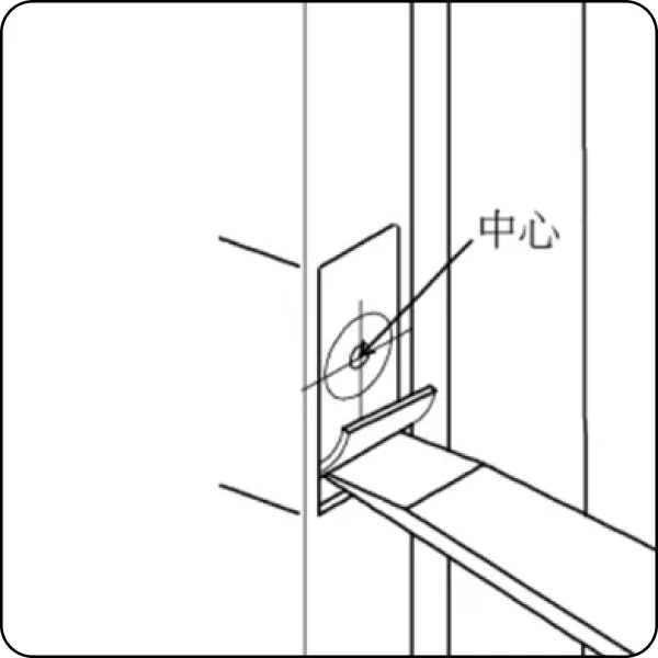
For the latch faceplate, chisel a recess:
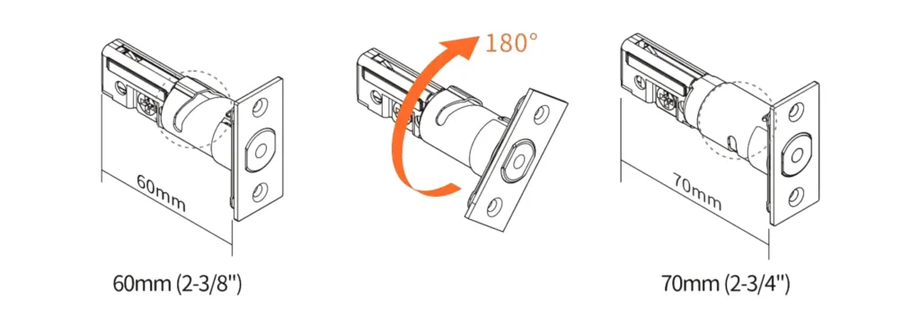
Rotate the latch to adjust the backset to 60 mm or 70 mm.
Follow our step-by-step video guide to install your SGUDA smart lock.
Follow the complete installation steps, from door preparation to final setup.
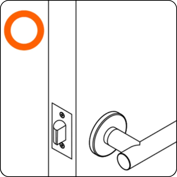
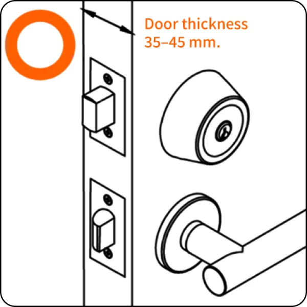
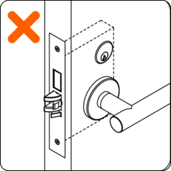
Ensure the lock fits the door perfectly.
Contact SGUDA official with photos for a professional evaluation.
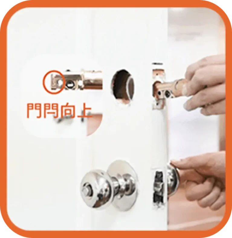
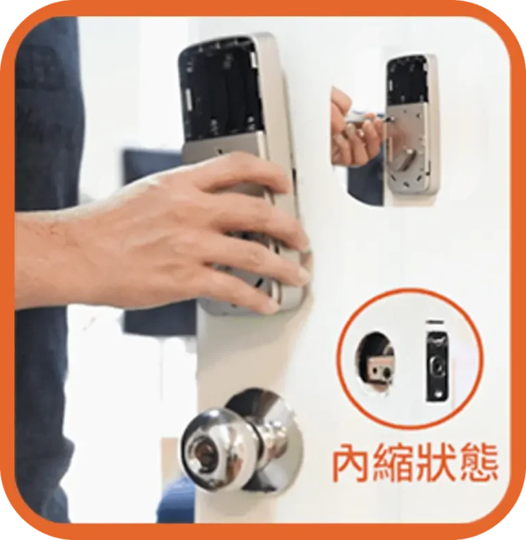
Rotate the deadbolt to adjust its length, with the latch facing upward.
Insert the deadbolt into the door. Make sure the center of the door hole is horizontally aligned, then secure it with screws.
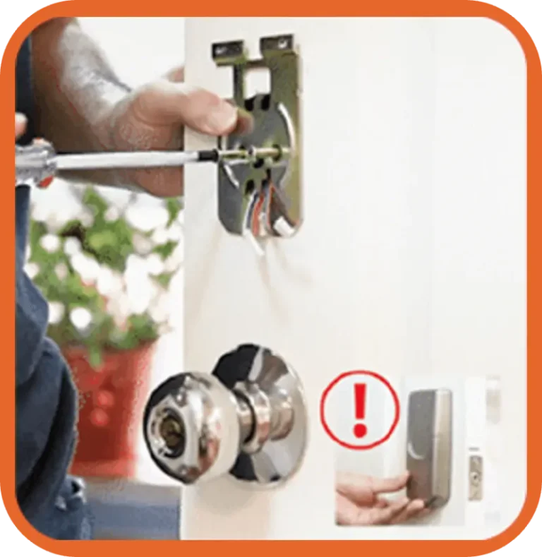
Pass the cable under the latch and insert the torque blade horizontally.
Ensure the internal protrusion faces upward.
Thread the cable through the plate and secure with 2 long screws.
Hold the exterior assembly firmly and do not pull the wires.
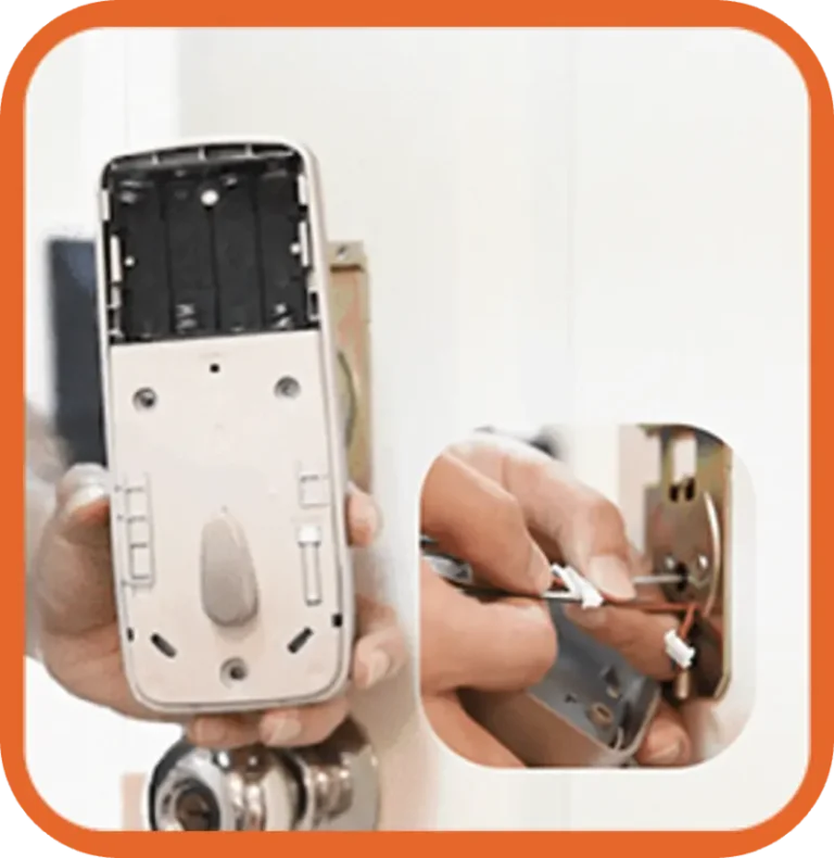
Match cable colors to connect the assemblies.
Insert connectors vertically and fully to ensure a stable connection.
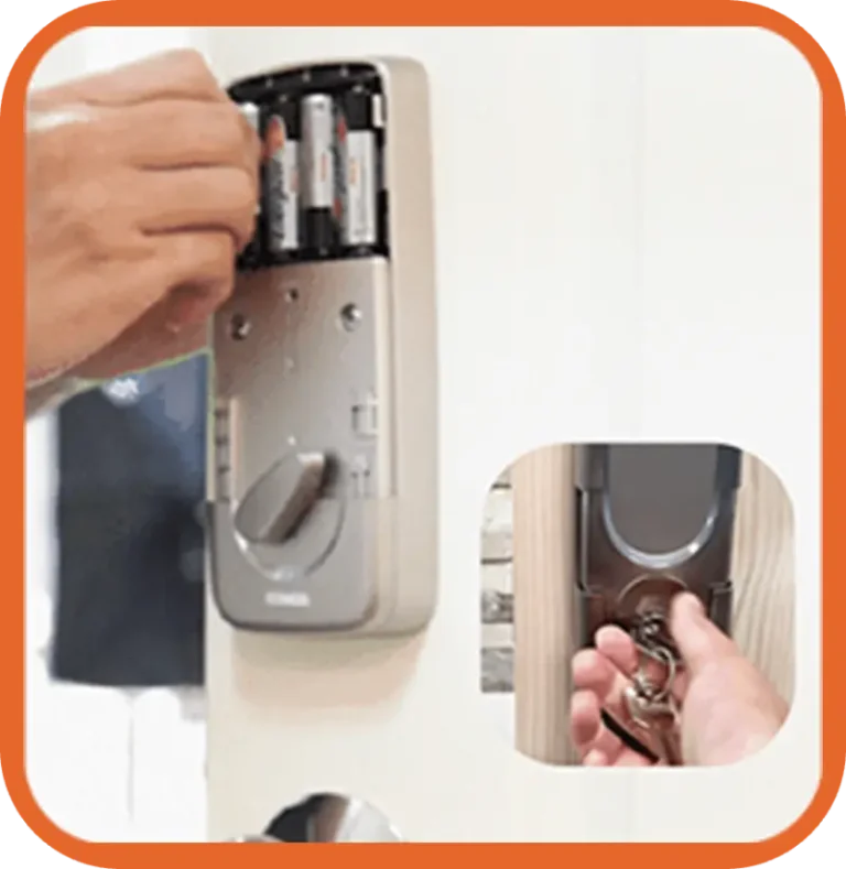
Set the thumbturn to “unlocked” and retract the latch.
Fit the interior assembly and secure with 3 short screws.
Install alkaline batteries and replace the cover. Test the thumbturn and key for smooth rotation.
(Note: Leakage is not covered by warranty.)
Download the SGUDA APP and pair it with the lock to test all functions.

Manage your cookie preferences below:
Essential cookies enable basic functions and are necessary for the proper function of the website.
These cookies are needed for adding comments on this website.
Google Tag Manager simplifies the management of marketing tags on your website without code changes.
Statistics cookies collect information anonymously. This information helps us understand how visitors use our website.
Google Analytics is a powerful tool that tracks and analyzes website traffic for informed marketing decisions.
Service URL: policies.google.com (opens in a new window)
Marketing cookies are used to follow visitors to websites. The intention is to show ads that are relevant and engaging to the individual user.
Google Ads is an online advertising platform that enables businesses to create targeted ads displayed on Google search results and partner sites.
Service URL: policies.google.com (opens in a new window)